Guides, tips and insights from the team at 3dprintwell.co.uk
Post 01 / 05
How to Prepare Your CAD File for 3D Printing (A Beginner's Guide)
3D PrintWell Team8 min readBeginner
Photo: Unsplash
You have an idea, you have a design — but when you send the file to a 3D printing service, something goes wrong. Sound familiar? The culprit is almost always file preparation. Here's everything you need to know to get it right the first time.
Start With the Right File Format
Most 3D printing services — including us here at 3D PrintWell — work with STL files as the standard. STL (Standard Tessellation Language) converts your 3D model into a mesh of triangles that slicing software can understand. Almost every CAD application can export to STL, including Fusion 360, SolidWorks, Blender, Tinkercad, and FreeCAD.
Increasingly, 3MF files are becoming preferred over STL because they retain colour, material, and scale data that STL strips away. If your software supports 3MF export, it's worth using.
We also accept STEP and OBJ files — useful if you need us to make minor adjustments before printing.
Check Your Model Is Watertight (Manifold)
A watertight model means every surface is fully closed — there are no holes, gaps, or overlapping faces. Think of it like a container: if you filled it with water, none should leak out. Slicing software gets confused by non-manifold geometry and can produce print errors or simply refuse to process the file.
The easiest way to check and fix this is with a free tool called Meshmixer (by Autodesk) or the online repair tool at Netfabb. Many slicers like PrusaSlicer and Bambu Studio also have basic auto-repair built in.
Quick tipIf you're working in Fusion 360, always export from the "Bodies" folder rather than the component level to reduce geometry errors.
Get Your Scale Right
This is the number one mistake we see. Always verify your model is in the correct units before exporting. STL files don't carry unit data — so a model designed in millimetres might import into the slicer as inches, making it 25× too large.
Best practice: design in millimetres and confirm the exported dimensions match your intended real-world size before sending. We always check this at our end, but confirming it saves time for everyone.
Think About Wall Thickness
For FDM printing, walls need to be at least 1.2mm thick (ideally 1.6mm or more) to print reliably. Thinner walls may not form correctly because the nozzle diameter determines the minimum printable line width — typically 0.4mm, with most walls requiring at least 2–3 lines.
For resin printing, you can go thinner — down to around 0.5mm — but very thin sections are fragile and prone to warping post-cure.
Consider Overhangs and Supports
FDM printers struggle to print angles steeper than around 45° without support structures. If your model has significant overhangs — like a T-shape, a horizontal hole, or a bridge — it will need supports, which are removed after printing and can leave surface marks.
Where possible, orient your model to minimise overhangs. We'll always advise on the best print orientation when you get in touch — it's often a simple rotation that makes a big difference to surface quality and material use.
Summary Checklist
Export as STL or 3MF
Check the file is watertight (manifold) — use Meshmixer or Netfabb
Confirm your model is scaled correctly in millimetres
Ensure wall thickness is at least 1.2mm for FDM, 0.5mm for resin
Minimise overhangs or plan for support removal
Send us a reference image or sketch if you have one — it helps enormously
Not sure if your file is ready?
Send it to us anyway. We review every file before printing and will flag any issues, suggest fixes, and advise on the best approach — all as part of our free quote process. No CAD experience required.
Ready to get your design printed? Get a free, no-obligation quote from the 3D PrintWell team.
How to Choose the Right 3D Printing Material for Your Project
3D PrintWell Team9 min readBeginner–Intermediate
Photo: Unsplash
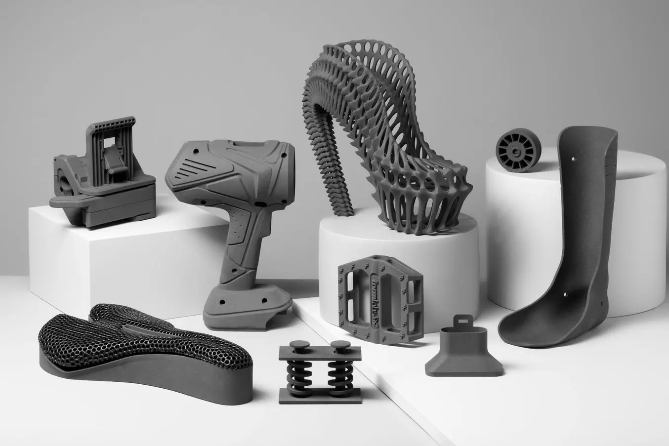
Material choice is one of the most consequential decisions in any 3D printing project. Get it right and your part performs exactly as intended. Get it wrong and you'll have a beautiful-looking object that snaps, warps, melts, or simply doesn't fit its purpose. Here's a practical guide to the most common materials and when to use each one.
PLA — The Everyday Workhorse
Polylactic Acid (PLA) is the most widely used FDM filament for good reason. It's easy to print, produces excellent surface quality, comes in virtually every colour, and is derived from renewable sources like cornstarch. For prototypes, display models, enclosures, and anything that won't face significant stress or heat, PLA is the default choice.
Its main limitation is heat resistance — PLA softens at around 60°C, which rules it out for anything near a hot environment (car interiors, outdoor use in summer, near electronics that run warm).
Best for
Prototypes and concept models
Display items and props
Low-stress functional parts
Models, miniatures, and decorative pieces
PETG — The Versatile Middle Ground
PETG bridges the gap between PLA's printability and ABS's toughness. It's stronger, more impact-resistant, and handles temperatures up to around 80°C — making it suitable for a much wider range of applications. It also has excellent layer adhesion, which means printed parts are less likely to delaminate under stress.
PETG is slightly more flexible than PLA, which is often an advantage — it bends before it breaks rather than shattering. It's also food-safe when printed correctly, though we'd always recommend a food-safe coating for anything in direct food contact.
Best for
Functional mechanical parts
Outdoor-use items
Electronics enclosures
Anything requiring impact resistance
ABS — The Engineering Stalwart
ABS (Acrylonitrile Butadiene Styrene) is the material LEGO bricks are made from — which tells you everything about its toughness and dimensional stability. It handles temperatures up to around 100°C and can be post-processed (sanded, painted, acetone-smoothed) to achieve a very clean finish.
The trade-off is that ABS is trickier to print — it warps on cooling, produces fumes, and requires an enclosed printer. At 3D PrintWell we have the equipment to handle ABS reliably, but it's worth being aware of why it costs slightly more than PLA.
Best for
High-temperature environments
Parts requiring post-processing or painting
Automotive and industrial applications
TPU — When You Need Flex
TPU (Thermoplastic Polyurethane) is a rubber-like flexible filament, and it opens up a whole category of applications that rigid plastics simply can't cover: gaskets, grips, seals, wearable components, cable tidies, and shock-absorbing mounts.
It's tougher than it looks — TPU is highly abrasion-resistant and can take significant repeated stress. Shore hardness varies by grade; we can advise on the right flexibility for your application.
Best for
Flexible enclosures and cases
Gaskets and seals
Grips and ergonomic components
Wearables and medical device components
Resin — When Detail Is Everything
Resin printing (SLA/MSLA) produces a level of surface detail that FDM simply can't match. Layer lines are virtually invisible, fine features down to 0.1mm are achievable, and surface quality is exceptional straight off the printer. The trade-off is brittleness — standard resins are more fragile than FDM plastics, though engineering resins with improved toughness are available.
Resin is the go-to for miniatures, jewellery masters, dental models, optics components, and any application where surface quality or fine detail is the priority.
Quick Comparison
Material
Strength
Heat Resistance
Detail
Best Use
PLA
Medium
Low (60°C)
Good
Prototypes, display
PETG
High
Medium (80°C)
Good
Functional parts
ABS
High
High (100°C)
Medium
Engineering, automotive
TPU
Flexible
Medium
Medium
Gaskets, grips, flex parts
Resin
Medium
Medium
Excellent
Detail, miniatures, optics
Not sure which material is right for you?
Tell us what your part needs to do and we'll recommend the best material — and often a better option you might not have considered. That's what makes working with a specialist service worthwhile.
Get expert material advice and a free quote for your project.
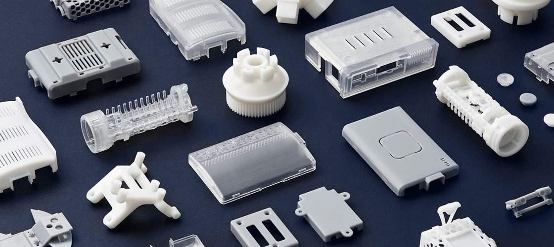
You have a product idea. Maybe it's a new component, a consumer gadget, a custom housing, or a replacement part. Getting a physical prototype made used to mean expensive tooling, long lead times, and minimum order quantities. 3D printing has changed all of that — here's exactly how the process works when you use a UK service like 3D PrintWell.
Step 1 — Define What You Need From the Prototype
Before anything else, it's worth being clear about the prototype's purpose. Is this a visual model for a presentation or investor pitch? A functional prototype that needs to fit, move, or withstand force? A form-check prototype to test ergonomics and proportions? Each has different requirements that will influence material choice, resolution, and cost.
You don't need to have all the answers — that's what our consultation process is for. But having a clear sense of the prototype's job helps us guide you towards the right approach.
Step 2 — Prepare (or Describe) Your Design
If you have a CAD file, brilliant — send it over in STL, STEP, or 3MF format. If you don't, that's fine too. We regularly work from:
Sketches (even hand-drawn ones photographed on a phone)
Reference photos of an existing object you'd like reproduced or modified
A written description with rough dimensions
A physical object you'd like 3D scanned and replicated
We can help with design adjustments and minor modelling — though for complex original designs we'd recommend working with a product designer first.
Step 3 — Get a Quote
Contact us via the quote page, email, or WhatsApp. We'll review your brief and come back with a clear quote covering material, print time, post-processing, and delivery. There's no obligation and no jargon.
Pricing for a prototype varies enormously depending on size, complexity, and material — a small functional component might be under £20, while a large multi-part assembly could be several hundred pounds. We'll always give you a transparent breakdown.
Pro tipIf budget is tight, ask us about printing in PLA first for a form/fit check, then upgrading to a functional material once the design is finalised. It can significantly reduce overall prototyping cost.
Step 4 — We Print and Post-Process
Once you've approved the quote, we get to work. Depending on complexity, most prototypes are printed within 1–3 working days. Post-processing — support removal, sanding, priming, painting, or assembly — is carried out by hand and is included where specified in the quote.
We use Bambu Lab printers for FDM work, which produce excellent dimensional accuracy and surface quality. For resin, we use MSLA printers capable of layer heights down to 0.05mm.
Step 5 — Delivery Anywhere in the UK
We ship prototypes to anywhere in the United Kingdom via tracked delivery. Most customers outside Northamptonshire receive their parts within 1–2 days of dispatch. We package parts carefully to prevent transit damage — something that matters more than it might seem for fragile resin prints or thin-walled models.
If you're local to Northamptonshire, you're also welcome to collect in person — and we're always happy to talk through the project face to face.
What Does a UK 3D Printing Service Cost?
Cost is determined by four main factors: volume of material used, print time, material type, and post-processing required. A rough guide:
Small parts (under 50mm) in PLA — typically £8–£25
Medium parts (50–150mm) in PETG or ABS — typically £20–£80
Large or complex multi-part assemblies — quoted individually
Resin parts — typically 20–40% more than equivalent FDM due to material cost
These are indicative figures — get in touch for an accurate quote for your specific project.
Based anywhere in the UK?
3D PrintWell serves customers from London to Edinburgh, Cardiff to Belfast. Wherever you are, we can have your prototype in your hands within a few days. Get a free quote and we'll take it from there.
Ready to turn your idea into something you can hold? Let's talk.
How to Use 3D Scanning to Reverse Engineer a Broken Part
3D PrintWell Team8 min readIntermediate
Photo: Unsplash
A machine goes down because a plastic bracket snapped. The manufacturer is out of business. The part number draws a blank. Sound familiar? 3D scanning combined with 3D printing is now one of the most practical solutions for exactly this problem — here's how the process works.
What Is Reverse Engineering?
Reverse engineering means taking an existing physical object and working backwards to create a digital model of it — without having the original design files. It's used across manufacturing, automotive, aerospace, heritage conservation, and product repair. With a 3D scanner and the right software, what once took days of manual measurement can often be done in hours.
When Does It Make Sense?
3D scanning for reverse engineering is particularly valuable when:
A spare part is no longer manufactured or available
You want to reproduce a legacy component for a machine or vehicle
You're designing a new product that needs to interface with an existing physical object
You want to create a digital archive of an important physical asset
You need to inspect and compare a manufactured part against its original specification
How 3D Scanning Works
A 3D scanner captures the surface geometry of an object as a dense point cloud — millions of individual coordinate measurements taken from multiple angles. These points are then stitched together to form a mesh, which can be cleaned, refined, and converted into a usable CAD model.
At 3D PrintWell we use a combination of structured light scanning for precise small-to-medium objects and photogrammetry for larger objects or environments. Each technique has its strengths, and we'll recommend the right approach for your specific part.
What photogrammetry meansPhotogrammetry uses overlapping photographs taken from many angles to reconstruct a 3D model. It's particularly effective for organic shapes, large objects, and anything where a physical scanner would be difficult to manoeuvre.
From Scan to Printable Part — Step by Step
The process from broken part to replacement in hand typically looks like this:
Send us the part — or bring it in if you're local to Northamptonshire. We'll assess whether it's suitable for scanning (very shiny or transparent surfaces sometimes need a light coating spray first).
We scan it — capturing as much surface data as possible, including undercuts and internal features where accessible.
Mesh cleanup — the raw scan data is cleaned of noise, holes are filled, and the mesh is refined.
CAD conversion — for engineering parts, we convert the mesh to a parametric CAD model (STEP format), which allows dimensions to be adjusted and tolerances set correctly.
Print the replacement — we print in the most appropriate material for the part's function. For structural parts, PETG or ABS are common choices; for flexible components, TPU.
Test fit and iterate — if the first print reveals any dimensional discrepancies, we adjust the model and reprint. Most parts are right first time; complex assemblies may need one iteration.
Accuracy and Tolerances
Modern structured light scanning achieves accuracies of 0.05mm or better — more than sufficient for most mechanical parts. FDM printing is typically accurate to ±0.2mm, which is acceptable for most applications but worth considering for precision-fit components like bearings or shafts.
Where tight tolerances are critical, we'll design in the appropriate clearance or recommend resin printing for higher dimensional accuracy.
Real Example — What We've Done
We've used this process for everything from broken camera rig brackets (the Channel 5 project you might have seen on our homepage) to vintage industrial machine components, custom automotive brackets, and specialist electronics enclosures. The common thread is that the part either no longer exists commercially or would cost a fortune to have tooled conventionally.
Have a broken part you can't source?
Send us a photo and a description — we'll let you know quickly whether 3D scanning and printing is the right approach, and what it's likely to cost. Based anywhere in the UK, we can work remotely and ship the finished part directly to you.
Got a part that needs reverse engineering? Let's take a look.
How to Design for FDM Printing — Common Mistakes and How to Avoid Them
3D PrintWell Team10 min readIntermediate
Photo: Unsplash
FDM (Fused Deposition Modelling) is the most widely used 3D printing technology in the world — but it has quirks. Understanding how the process works helps you design parts that print reliably and perform well. Here are the most common mistakes we see, and exactly how to avoid them.
Understanding the FDM Process First
FDM works by melting plastic filament and depositing it layer by layer, building up a part from the bed upwards. This means every part is inherently anisotropic — stronger in the X and Y axes (along each layer) than in the Z axis (between layers). Designing with this in mind is fundamental to getting good functional results.
Mistake 1 — Ignoring Print Orientation
Print orientation is the single most influential decision in FDM, and it's often overlooked entirely. The orientation determines where layer lines fall relative to the stresses your part will face, where supports are needed, and what the surface quality looks like on each face.
The fix: Think about where your part will experience the most force. Layer lines should run parallel to that force, not perpendicular to it. A bolt hole printed vertically (so layers wrap around it) will be significantly stronger than one printed horizontally.
Mistake 2 — Walls That Are Too Thin
Standard FDM nozzles are 0.4mm in diameter, and most parts are printed with 2–4 perimeter lines. This means your minimum wall thickness for a reliable print is typically 0.8mm (two perimeters), with 1.2–1.6mm being more robust for functional parts.
The fix: Design walls to be at least 1.2mm thick. For anything load-bearing, 2mm or more gives much better results. Also avoid walls that are a non-multiple of your nozzle width — a 1.0mm wall with a 0.4mm nozzle creates an awkward 2.5 perimeters that slicers handle inconsistently.
Rule of thumbDesign walls in multiples of 0.4mm: 0.8mm, 1.2mm, 1.6mm, 2.0mm. This gives the slicer clean perimeter counts and more predictable results.
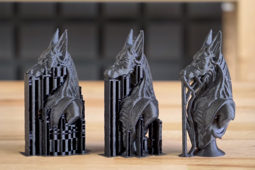
Mistake 3 — Overhangs Without Support Planning
FDM can't print in mid-air. Overhangs beyond about 45° from vertical require support structures — temporary printed scaffolding that's removed after printing. Supports add print time, cost, and always leave some surface marking where they were attached.
The fix: Design to minimise overhangs where possible. Chamfer instead of fillet on bottom edges. Use the 45° rule as your guide. Where you must have overhangs, design in break-away points to make support removal easier. Alternatively, split a complex part into two simpler pieces and bond them after printing — often a better solution.
Mistake 4 — Holes That Are Too Small or Untolerated
Printed holes always come out slightly smaller than designed due to material shrinkage and the circular approximation in the slicer. A 5mm hole will typically print at around 4.7–4.8mm without compensation.
The fix: Add 0.2mm to the diameter of precision holes to account for shrinkage. For holes that need to accept a bolt or shaft, we recommend either designing for a press-fit (hole slightly smaller than shaft) and drilling to final size, or designing clearance holes 0.3–0.5mm oversize.
Mistake 5 — Flat Surfaces on the Print Bed
Large flat surfaces in contact with the print bed can warp — particularly in ABS and ASA, but also in PETG with some geometries. The corners lift as the part cools unevenly, leading to a distorted base and potential print failure.
The fix: Add a chamfer or fillet to the bottom edges of large flat parts. Use a brim in the slicer settings to increase adhesion. For particularly warp-prone materials, design the part so the largest flat face is on the bed — and we'll use the appropriate adhesion and enclosure settings on our end.
FDM is dimensionally accurate to approximately ±0.2mm in X and Y, and ±0.3mm in Z. This is perfectly adequate for most applications — but it's not injection moulding. If you design mating parts with 0.05mm clearances, they won't fit.
The fix: Allow at least 0.3mm clearance for parts that need to slide together, and 0.1–0.2mm for press-fits. Always print a test piece first if precise mating is required.
Summary — FDM Design Rules at a Glance
Feature
Recommended Value
Why
Min wall thickness
1.2mm (2mm for structural)
Nozzle width multiples
Max unsupported overhang
45°
Layer-to-layer bridge limit
Hole tolerance (add to diameter)
+0.2mm
Shrinkage compensation
Clearance fit
0.3mm per side
Dimensional tolerance
Press fit
0.1–0.15mm interference
Layer variability
Min detail feature
0.8mm
Nozzle width limit
We'll always flag design issues before printing.
When you submit a file to 3D PrintWell, our team reviews it for printability before a single layer is laid down. If we spot something that will cause a problem, we'll tell you — and suggest the fix. That's the advantage of working with people who print all day, every day.
Have a design you'd like us to review? Send it over and we'll take a look as part of your free quote.
Guides, tips and insights from the team at 3dprintwell.co.uk
Post 01 / 05
How to Prepare Your CAD File for 3D Printing (A Beginner's Guide)
3D PrintWell Team8 min readBeginner
Photo: Unsplash
You have an idea, you have a design — but when you send the file to a 3D printing service, something goes wrong. Sound familiar? The culprit is almost always file preparation. Here's everything you need to know to get it right the first time.
Start With the Right File Format
Most 3D printing services — including us here at 3D PrintWell — work with STL files as the standard. STL (Standard Tessellation Language) converts your 3D model into a mesh of triangles that slicing software can understand. Almost every CAD application can export to STL, including Fusion 360, SolidWorks, Blender, Tinkercad, and FreeCAD.
Increasingly, 3MF files are becoming preferred over STL because they retain colour, material, and scale data that STL strips away. If your software supports 3MF export, it's worth using.
We also accept STEP and OBJ files — useful if you need us to make minor adjustments before printing.
Check Your Model Is Watertight (Manifold)
A watertight model means every surface is fully closed — there are no holes, gaps, or overlapping faces. Think of it like a container: if you filled it with water, none should leak out. Slicing software gets confused by non-manifold geometry and can produce print errors or simply refuse to process the file.
The easiest way to check and fix this is with a free tool called Meshmixer (by Autodesk) or the online repair tool at Netfabb. Many slicers like PrusaSlicer and Bambu Studio also have basic auto-repair built in.
Quick tipIf you're working in Fusion 360, always export from the "Bodies" folder rather than the component level to reduce geometry errors.
Get Your Scale Right
This is the number one mistake we see. Always verify your model is in the correct units before exporting. STL files don't carry unit data — so a model designed in millimetres might import into the slicer as inches, making it 25× too large.
Best practice: design in millimetres and confirm the exported dimensions match your intended real-world size before sending. We always check this at our end, but confirming it saves time for everyone.
Think About Wall Thickness
For FDM printing, walls need to be at least 1.2mm thick (ideally 1.6mm or more) to print reliably. Thinner walls may not form correctly because the nozzle diameter determines the minimum printable line width — typically 0.4mm, with most walls requiring at least 2–3 lines.
For resin printing, you can go thinner — down to around 0.5mm — but very thin sections are fragile and prone to warping post-cure.
Consider Overhangs and Supports
FDM printers struggle to print angles steeper than around 45° without support structures. If your model has significant overhangs — like a T-shape, a horizontal hole, or a bridge — it will need supports, which are removed after printing and can leave surface marks.
Where possible, orient your model to minimise overhangs. We'll always advise on the best print orientation when you get in touch — it's often a simple rotation that makes a big difference to surface quality and material use.
Summary Checklist
Export as STL or 3MF
Check the file is watertight (manifold) — use Meshmixer or Netfabb
Confirm your model is scaled correctly in millimetres
Ensure wall thickness is at least 1.2mm for FDM, 0.5mm for resin
Minimise overhangs or plan for support removal
Send us a reference image or sketch if you have one — it helps enormously
Not sure if your file is ready?
Send it to us anyway. We review every file before printing and will flag any issues, suggest fixes, and advise on the best approach — all as part of our free quote process. No CAD experience required.
Ready to get your design printed? Get a free, no-obligation quote from the 3D PrintWell team.
How to Choose the Right 3D Printing Material for Your Project
3D PrintWell Team9 min readBeginner–Intermediate
Photo: Unsplash
Material choice is one of the most consequential decisions in any 3D printing project. Get it right and your part performs exactly as intended. Get it wrong and you'll have a beautiful-looking object that snaps, warps, melts, or simply doesn't fit its purpose. Here's a practical guide to the most common materials and when to use each one.
PLA — The Everyday Workhorse
Polylactic Acid (PLA) is the most widely used FDM filament for good reason. It's easy to print, produces excellent surface quality, comes in virtually every colour, and is derived from renewable sources like cornstarch. For prototypes, display models, enclosures, and anything that won't face significant stress or heat, PLA is the default choice.
Its main limitation is heat resistance — PLA softens at around 60°C, which rules it out for anything near a hot environment (car interiors, outdoor use in summer, near electronics that run warm).
Best for
Prototypes and concept models
Display items and props
Low-stress functional parts
Models, miniatures, and decorative pieces
PETG — The Versatile Middle Ground
PETG bridges the gap between PLA's printability and ABS's toughness. It's stronger, more impact-resistant, and handles temperatures up to around 80°C — making it suitable for a much wider range of applications. It also has excellent layer adhesion, which means printed parts are less likely to delaminate under stress.
PETG is slightly more flexible than PLA, which is often an advantage — it bends before it breaks rather than shattering. It's also food-safe when printed correctly, though we'd always recommend a food-safe coating for anything in direct food contact.
Best for
Functional mechanical parts
Outdoor-use items
Electronics enclosures
Anything requiring impact resistance
ABS — The Engineering Stalwart
ABS (Acrylonitrile Butadiene Styrene) is the material LEGO bricks are made from — which tells you everything about its toughness and dimensional stability. It handles temperatures up to around 100°C and can be post-processed (sanded, painted, acetone-smoothed) to achieve a very clean finish.
The trade-off is that ABS is trickier to print — it warps on cooling, produces fumes, and requires an enclosed printer. At 3D PrintWell we have the equipment to handle ABS reliably, but it's worth being aware of why it costs slightly more than PLA.
Best for
High-temperature environments
Parts requiring post-processing or painting
Automotive and industrial applications
TPU — When You Need Flex
TPU (Thermoplastic Polyurethane) is a rubber-like flexible filament, and it opens up a whole category of applications that rigid plastics simply can't cover: gaskets, grips, seals, wearable components, cable tidies, and shock-absorbing mounts.
It's tougher than it looks — TPU is highly abrasion-resistant and can take significant repeated stress. Shore hardness varies by grade; we can advise on the right flexibility for your application.
Best for
Flexible enclosures and cases
Gaskets and seals
Grips and ergonomic components
Wearables and medical device components
Resin — When Detail Is Everything
Resin printing (SLA/MSLA) produces a level of surface detail that FDM simply can't match. Layer lines are virtually invisible, fine features down to 0.1mm are achievable, and surface quality is exceptional straight off the printer. The trade-off is brittleness — standard resins are more fragile than FDM plastics, though engineering resins with improved toughness are available.
Resin is the go-to for miniatures, jewellery masters, dental models, optics components, and any application where surface quality or fine detail is the priority.
Quick Comparison
Material
Strength
Heat Resistance
Detail
Best Use
PLA
Medium
Low (60°C)
Good
Prototypes, display
PETG
High
Medium (80°C)
Good
Functional parts
ABS
High
High (100°C)
Medium
Engineering, automotive
TPU
Flexible
Medium
Medium
Gaskets, grips, flex parts
Resin
Medium
Medium
Excellent
Detail, miniatures, optics
Not sure which material is right for you?
Tell us what your part needs to do and we'll recommend the best material — and often a better option you might not have considered. That's what makes working with a specialist service worthwhile.
Get expert material advice and a free quote for your project.
You have a product idea. Maybe it's a new component, a consumer gadget, a custom housing, or a replacement part. Getting a physical prototype made used to mean expensive tooling, long lead times, and minimum order quantities. 3D printing has changed all of that — here's exactly how the process works when you use a UK service like 3D PrintWell.
Step 1 — Define What You Need From the Prototype
Before anything else, it's worth being clear about the prototype's purpose. Is this a visual model for a presentation or investor pitch? A functional prototype that needs to fit, move, or withstand force? A form-check prototype to test ergonomics and proportions? Each has different requirements that will influence material choice, resolution, and cost.
You don't need to have all the answers — that's what our consultation process is for. But having a clear sense of the prototype's job helps us guide you towards the right approach.
Step 2 — Prepare (or Describe) Your Design
If you have a CAD file, brilliant — send it over in STL, STEP, or 3MF format. If you don't, that's fine too. We regularly work from:
Sketches (even hand-drawn ones photographed on a phone)
Reference photos of an existing object you'd like reproduced or modified
A written description with rough dimensions
A physical object you'd like 3D scanned and replicated
We can help with design adjustments and minor modelling — though for complex original designs we'd recommend working with a product designer first.
Step 3 — Get a Quote
Contact us via the quote page, email, or WhatsApp. We'll review your brief and come back with a clear quote covering material, print time, post-processing, and delivery. There's no obligation and no jargon.
Pricing for a prototype varies enormously depending on size, complexity, and material — a small functional component might be under £20, while a large multi-part assembly could be several hundred pounds. We'll always give you a transparent breakdown.
Pro tipIf budget is tight, ask us about printing in PLA first for a form/fit check, then upgrading to a functional material once the design is finalised. It can significantly reduce overall prototyping cost.
Step 4 — We Print and Post-Process
Once you've approved the quote, we get to work. Depending on complexity, most prototypes are printed within 1–3 working days. Post-processing — support removal, sanding, priming, painting, or assembly — is carried out by hand and is included where specified in the quote.
We use Bambu Lab printers for FDM work, which produce excellent dimensional accuracy and surface quality. For resin, we use MSLA printers capable of layer heights down to 0.05mm.
Step 5 — Delivery Anywhere in the UK
We ship prototypes to anywhere in the United Kingdom via tracked delivery. Most customers outside Northamptonshire receive their parts within 1–2 days of dispatch. We package parts carefully to prevent transit damage — something that matters more than it might seem for fragile resin prints or thin-walled models.
If you're local to Northamptonshire, you're also welcome to collect in person — and we're always happy to talk through the project face to face.
What Does a UK 3D Printing Service Cost?
Cost is determined by four main factors: volume of material used, print time, material type, and post-processing required. A rough guide:
Small parts (under 50mm) in PLA — typically £8–£25
Medium parts (50–150mm) in PETG or ABS — typically £20–£80
Large or complex multi-part assemblies — quoted individually
Resin parts — typically 20–40% more than equivalent FDM due to material cost
These are indicative figures — get in touch for an accurate quote for your specific project.
Based anywhere in the UK?
3D PrintWell serves customers from London to Edinburgh, Cardiff to Belfast. Wherever you are, we can have your prototype in your hands within a few days. Get a free quote and we'll take it from there.
Ready to turn your idea into something you can hold? Let's talk.
How to Use 3D Scanning to Reverse Engineer a Broken Part
3D PrintWell Team8 min readIntermediate
Photo: Unsplash
A machine goes down because a plastic bracket snapped. The manufacturer is out of business. The part number draws a blank. Sound familiar? 3D scanning combined with 3D printing is now one of the most practical solutions for exactly this problem — here's how the process works.
What Is Reverse Engineering?
Reverse engineering means taking an existing physical object and working backwards to create a digital model of it — without having the original design files. It's used across manufacturing, automotive, aerospace, heritage conservation, and product repair. With a 3D scanner and the right software, what once took days of manual measurement can often be done in hours.
When Does It Make Sense?
3D scanning for reverse engineering is particularly valuable when:
A spare part is no longer manufactured or available
You want to reproduce a legacy component for a machine or vehicle
You're designing a new product that needs to interface with an existing physical object
You want to create a digital archive of an important physical asset
You need to inspect and compare a manufactured part against its original specification
How 3D Scanning Works
A 3D scanner captures the surface geometry of an object as a dense point cloud — millions of individual coordinate measurements taken from multiple angles. These points are then stitched together to form a mesh, which can be cleaned, refined, and converted into a usable CAD model.
At 3D PrintWell we use a combination of structured light scanning for precise small-to-medium objects and photogrammetry for larger objects or environments. Each technique has its strengths, and we'll recommend the right approach for your specific part.
What photogrammetry meansPhotogrammetry uses overlapping photographs taken from many angles to reconstruct a 3D model. It's particularly effective for organic shapes, large objects, and anything where a physical scanner would be difficult to manoeuvre.
From Scan to Printable Part — Step by Step
The process from broken part to replacement in hand typically looks like this:
Send us the part — or bring it in if you're local to Northamptonshire. We'll assess whether it's suitable for scanning (very shiny or transparent surfaces sometimes need a light coating spray first).
We scan it — capturing as much surface data as possible, including undercuts and internal features where accessible.
Mesh cleanup — the raw scan data is cleaned of noise, holes are filled, and the mesh is refined.
CAD conversion — for engineering parts, we convert the mesh to a parametric CAD model (STEP format), which allows dimensions to be adjusted and tolerances set correctly.
Print the replacement — we print in the most appropriate material for the part's function. For structural parts, PETG or ABS are common choices; for flexible components, TPU.
Test fit and iterate — if the first print reveals any dimensional discrepancies, we adjust the model and reprint. Most parts are right first time; complex assemblies may need one iteration.
Accuracy and Tolerances
Modern structured light scanning achieves accuracies of 0.05mm or better — more than sufficient for most mechanical parts. FDM printing is typically accurate to ±0.2mm, which is acceptable for most applications but worth considering for precision-fit components like bearings or shafts.
Where tight tolerances are critical, we'll design in the appropriate clearance or recommend resin printing for higher dimensional accuracy.
Real Example — What We've Done
We've used this process for everything from broken camera rig brackets (the Channel 5 project you might have seen on our homepage) to vintage industrial machine components, custom automotive brackets, and specialist electronics enclosures. The common thread is that the part either no longer exists commercially or would cost a fortune to have tooled conventionally.
Have a broken part you can't source?
Send us a photo and a description — we'll let you know quickly whether 3D scanning and printing is the right approach, and what it's likely to cost. Based anywhere in the UK, we can work remotely and ship the finished part directly to you.
Got a part that needs reverse engineering? Let's take a look.
How to Design for FDM Printing — Common Mistakes and How to Avoid Them
3D PrintWell Team10 min readIntermediate
Photo: Unsplash
FDM (Fused Deposition Modelling) is the most widely used 3D printing technology in the world — but it has quirks. Understanding how the process works helps you design parts that print reliably and perform well. Here are the most common mistakes we see, and exactly how to avoid them.
Understanding the FDM Process First
FDM works by melting plastic filament and depositing it layer by layer, building up a part from the bed upwards. This means every part is inherently anisotropic — stronger in the X and Y axes (along each layer) than in the Z axis (between layers). Designing with this in mind is fundamental to getting good functional results.
Mistake 1 — Ignoring Print Orientation
Print orientation is the single most influential decision in FDM, and it's often overlooked entirely. The orientation determines where layer lines fall relative to the stresses your part will face, where supports are needed, and what the surface quality looks like on each face.
The fix: Think about where your part will experience the most force. Layer lines should run parallel to that force, not perpendicular to it. A bolt hole printed vertically (so layers wrap around it) will be significantly stronger than one printed horizontally.
Mistake 2 — Walls That Are Too Thin
Standard FDM nozzles are 0.4mm in diameter, and most parts are printed with 2–4 perimeter lines. This means your minimum wall thickness for a reliable print is typically 0.8mm (two perimeters), with 1.2–1.6mm being more robust for functional parts.
The fix: Design walls to be at least 1.2mm thick. For anything load-bearing, 2mm or more gives much better results. Also avoid walls that are a non-multiple of your nozzle width — a 1.0mm wall with a 0.4mm nozzle creates an awkward 2.5 perimeters that slicers handle inconsistently.
Rule of thumbDesign walls in multiples of 0.4mm: 0.8mm, 1.2mm, 1.6mm, 2.0mm. This gives the slicer clean perimeter counts and more predictable results.
Mistake 3 — Overhangs Without Support Planning
FDM can't print in mid-air. Overhangs beyond about 45° from vertical require support structures — temporary printed scaffolding that's removed after printing. Supports add print time, cost, and always leave some surface marking where they were attached.
The fix: Design to minimise overhangs where possible. Chamfer instead of fillet on bottom edges. Use the 45° rule as your guide. Where you must have overhangs, design in break-away points to make support removal easier. Alternatively, split a complex part into two simpler pieces and bond them after printing — often a better solution.
Mistake 4 — Holes That Are Too Small or Untolerated
Printed holes always come out slightly smaller than designed due to material shrinkage and the circular approximation in the slicer. A 5mm hole will typically print at around 4.7–4.8mm without compensation.
The fix: Add 0.2mm to the diameter of precision holes to account for shrinkage. For holes that need to accept a bolt or shaft, we recommend either designing for a press-fit (hole slightly smaller than shaft) and drilling to final size, or designing clearance holes 0.3–0.5mm oversize.
Mistake 5 — Flat Surfaces on the Print Bed
Large flat surfaces in contact with the print bed can warp — particularly in ABS and ASA, but also in PETG with some geometries. The corners lift as the part cools unevenly, leading to a distorted base and potential print failure.
The fix: Add a chamfer or fillet to the bottom edges of large flat parts. Use a brim in the slicer settings to increase adhesion. For particularly warp-prone materials, design the part so the largest flat face is on the bed — and we'll use the appropriate adhesion and enclosure settings on our end.
FDM is dimensionally accurate to approximately ±0.2mm in X and Y, and ±0.3mm in Z. This is perfectly adequate for most applications — but it's not injection moulding. If you design mating parts with 0.05mm clearances, they won't fit.
The fix: Allow at least 0.3mm clearance for parts that need to slide together, and 0.1–0.2mm for press-fits. Always print a test piece first if precise mating is required.
Summary — FDM Design Rules at a Glance
Feature
Recommended Value
Why
Min wall thickness
1.2mm (2mm for structural)
Nozzle width multiples
Max unsupported overhang
45°
Layer-to-layer bridge limit
Hole tolerance (add to diameter)
+0.2mm
Shrinkage compensation
Clearance fit
0.3mm per side
Dimensional tolerance
Press fit
0.1–0.15mm interference
Layer variability
Min detail feature
0.8mm
Nozzle width limit
We'll always flag design issues before printing.
When you submit a file to 3D PrintWell, our team reviews it for printability before a single layer is laid down. If we spot something that will cause a problem, we'll tell you — and suggest the fix. That's the advantage of working with people who print all day, every day.
Have a design you'd like us to review? Send it over and we'll take a look as part of your free quote.